Decoding IP Addressing used by network devices
TCP/IP internet is a virtual network consisting of multiple physical networks connected through routers. Every devices connected to a network is assigned an IP address.
IP address play an important role in the Internet Layer of the TCP/IP protocol layering model. It helps TCP/IP software hide physical network details making the internet looks like a single unified communication system.
IP Addressing
Every devices connected to the TCP/IP network is known as a end system or host and each of this system is assigned a unique identifier known as IP address so that these devices can use this address to communicate with each other.
IP addressing scheme used by the TCP/IP network also helps in routing the packet efficiently through the network. IP address is divided into two parts.
- Network Identifier: The prefix part of the IP address identifies the network to which the host is attached
- Host Identified: The suffix part of the IP address identifies the specific host on the network.
NOTE: Hosts witihin a same network share a common network prefix.
IP addresses assigned to devices have a fixed size (ie. 32 bits for IPv4 and 128 bits for IPv6) as shown below.
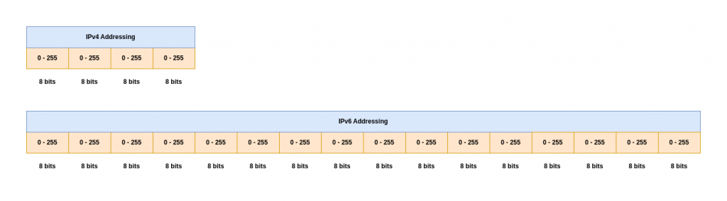
Now that we have a fixed size assigned to the IP address, the number of bits allocated for network id determine the size of the network and the number of bits allocated for the host id determine the number of hosts that could be allocated within that network.
The larger the number of bits allocated for network id, the smaller the number of hosts that could be allocated within that network and vice-versa.
IPv4 Traditional Classful Addressing Scheme
As mentioned a network consist of multiple sub networks connected to each other to form a global network of networks. Each network can either be small, medium or large based on the number of devices that needs to be accomodated.
To accomodate these different sizes of networks and hosts, classful addressing scheme was invented where-in a fixed number of bits were allocated for the network and host identification.
In the classful addressing scheme, each address is said to be self-identifying because the boundary between prefix and suffix can be computed from the address alone, without reference to external information.
| Type | Usage | Prefix | Net ID bits | Host ID bits | Example IP | Bit Representation |
|---|---|---|---|---|---|---|
| Class A | WAN | 0 | 7 | 24 | 10.50.13.40 | 00001010.00110010.00001101.00101000 |
| Class B | MAN | 10 | 14 | 16 | 172.16.0.1 | 10101100.00010000.00000000.00000001 |
| Class C | LAN | 110 | 21 | 8 | 192.168.1.10 | 11000000.10101000.00000001.00001010 |
| Class D | Multicast | 1110 | NA | NA | 224.0.0.1 | 11100000.00000000.00000000.00000001 |
| Class E | Experimental | 1111 | NA | NA | 240.0.0.1 | 11110000.00000000.00000000.00000001 |
IPv4 address are usually represented in the dotted decimal notation as shown in the “Example IP” column in the table above.
Class D IP addresses are special 32-bit addresses (ranging from 224.0.0.0 to 239.255.255.255) reserved for multicasting, a one-to-many communication method for sending data to groups of interested hosts simultaneously, ideal for streaming video/audio, with no subnet mask as they don’t define networks or hosts but group identifiers.
Class E IP addresses are a block of IPv4 addresses (240.0.0.0 to 255.255.255.255) reserved for experimental and future use. They are identified by the first four bits of the first octet being 1111, and lack defined network/host portions, making them inherently non-routable on the public internet by default.
Through classful addressing scheme was introduced to accomodate different sizes of network. The key problem with this type of addressing are as listed below.
- Address Waste: Fixed, large address blocks (Class A, B) meant most addresses went unused. For instance, a company needing 500 IPs would get a Class B (over 65,000 hosts), wasting tens of thousands of addresses.
- Address Depletion: The fast growth of the internet quickly exhausted the limited number of available Class A and B addresses.
- Inflexibility: A small organization growing slightly larger than a Class C (254 hosts) had to jump to a massive Class B without any middle ground.
Subnetting
In order to accomodate for these limitation, subnet addressing or subnetting was introduced. Subnetting allows a single network prefix to be used for multiple physical networks.
Subnet addressing takes advantage of the freedom by allowing a site to divide the host portion of their addresses among multiple networks.
Within Subnetting in picture we can now conceptualize it using the IP address scheme as shown below. Now the IP address can be divided into two portions internet portion and a local portion, where the internet portion identifies a site, possibly with multiple physical networks, and the local portion identifies a physical network and host at that site.
The local portion can further be divided into two fields that identify a physical network at the site and a host on that network.
This hierarchical addressing helps in routing the packets efficiently but it needs upfront planning and cannot be changed easily once established.
- Fixed Length Subnetting: Divides a network into subnets that all have the same size (same number of hosts) and use the same subnet mask.
- Variable Length Subnetting: Allows for different subnet sizes (and masks) within the same network, tailored to specific needs. The partition for each subnet and the values chosen for subnet numbers must be assigned carefully to avoid address ambiguity, a situation in which an address is interpreted differently on two physical networks.
- Subnet Mask: A subnet mask is a 32-bit number used with an IP address to divide it into network and host portions, telling devices which part identifies the network and which part identifies the specific device on that network, enabling efficient network management and segmentation. It works by using ‘1’s for the network part and ‘0’s for the host part, helping computers route data correctly within or outside their local subnet.
IPv4 Classless Addressing Scheme
The classless addressing scheme came into picture temporarily to address the issue with IP address exhaustion. This new scheme extends the idea used in subnet addressing to permit a network prefix to be an arbitrary length. This new technology is called a Classless Inter-Domain Routing (CIDR).
CIDR addresses are not self-identifying. CIDR notation, consists of a starting address in dotted decimal followed by a mask size in slash notation.
Example: 128.211.168.0 / 21 # where / 21 denotes an address mask with 21 bits set to 1
Classless IPv4 addressing, which is now used throughout the Internet, assigns each ISP a CIDR block and allows the ISP to partition addresses into contiguous subblocks, where the lowest address in a subblock starts at a power of two and the subblock contains a power of two addresses.
Private Network Addressing
When classless addressing was invented, the set of reserved IPv4 prefixes was redefined and extended. Here is the list of values of private addresses using CIDR.
- 10.0.0.0 / 8
- 172.16.0.0 / 12
- 192.168.0.0 / 16
- 169.254.0.0 / 16
IPv6 Addressing Scheme
An IPv4 address consist of 128 bits (ie. 16 octets) compared to IPv4 address which is 32 bits (ie. 4 octets). If we look at the number of addresses that can be assigned with 128 bits it’s almost 3.4 × 10^38.
>>> pow(2, 128)
340282366920938463463374607431768211456
IPv6 addresses are denoted using the colon hexadecimal notation rather than dotted decimal notation which is used for IPv4 addresses. Colon hex notation allows zero compression in which a string of repeated zeros is replaced by a pair of colons.
Example: FF05:0:0:0:0:0:0:B3 can be represented is short form as FF05::B3
IPv6 colon-hexadecimal notation can incorporate a dotted-decimal suffix as an alternative format to represent embedded IPv4 addresses in a mixed networking environment. The address uses hexadecimal values for the left-most 96 bits (six 16-bit groups) and dotted-decimal notation (standard IPv4 format) for the right-most 32 bits (four 8-bit values).
Example: 0:0:0:0:0:ffff:192.1.56.10
This representation allows IPv6 applications to communicate directly with IPv4 devices by representing the IPv4 address within the IPv6 structure.
IPv6 extends CIDR-like notation by allowing an address to be followed by a slash and an integer that specifies a number of bits.
IPv6 Address Space Assignment
The IPv6 address space has been divided into blocks of addresses analogous to the original classful scheme used with IPv4. The first 8 bits of an address are sufficient to identify the basic types.
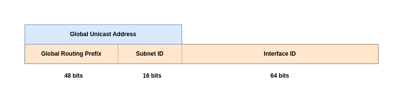
IPv6 Global Unicast Addresses (GUAs) are globally unique, routable internet addresses, analogous to public IPv4 addresses, used for devices needing internet access, starting with the prefix 2000::/3 (hexadecimal 2 or 3). They are structured with a 48-bit Global Routing Prefix (assigned by ISPs), a 16-bit Subnet ID (for internal network organization), and a 64-bit Interface ID (identifying the host). This hierarchical structure allows for efficient routing and aggregation, eliminating the need for Network Address Translation (NAT).
Example: 2001:db8:1234:5678:0221:2FFF:FEB5:6E10

2001:db8:1234 (First 48 bits): Global Routing Prefix.
5678 (Next 16 bits): Subnet ID.
0221:2FFF:FEB5:6E10 (Last 64 bits): Interface ID.
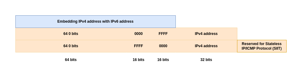
Any address that begins with 80 zero bits followed by 16 bits of all ones contains an IPv4 address in the low-order 32 bits. Thats one process followed for transitioning IPv4 addresses into IPv6. In addition to address embedding, packet translation is needed to convert between IPv4 and IPv6 packet formats.
As you may have noticed the last 64 bits in IPv6 address represents an Interface ID as a system or host can have multiple network interface cards attached to it. Also 64 bit suffix allocation for interface ID was chosen to be large enough to allow a hardware (MAC) address to be used as the unique ID. Embedding a hardware address in an IPv6 address makes finding the hardware address of a computer trivial.
The IPv6 standards specify exactly how to represent various forms of hardware addresses. In the simplest case, the hardware address is placed directly in the low-order bits of an IPv6 address; some formats use more complex transformations.
To avoid checksum mismatch, the IPv6 encoding of an IPv4 address has been chosen so that the 16-bit one’s complement checksum for both an IPv4 address and the IPv6 embedded version of the address are identical.
IPv6 provides a vast, globally routable address space (Global Unicast Addresses) for universal reachability, alongside link-local and unique local addresses for specific network segments, ensuring true end-to-end connectivity and simplifying network management without NAT.
Special Address
IPv4
- IPv4 network address: An IPv4 address that has a host ID of 0 is reserved to refer to the network.
- IPv4 direct broadcast address: An IPv4 address that has a host ID of all 1s is reserved for directed broad- cast† in which a packet is sent to all computers on a specific network
- IPv4 limited local network broadcast address: An IPv4 limited broadcast address consists of thirty-two 1 bits. A packet sent to the limited broadcast address will be broadcast across the local network, and can be used at startup before a computer learns its IP address.
- IPv4 Subnet broadcast address: A subnet broadcast address is used to broadcast on a single network within a site that uses subnetting. The address contains a network and subnet prefix and has all 1s in the host field.
- IPv4 all 0s source address: An address with thirty-two 0 bits is used as a temporary source address at startup before a host learns its IP address.
- IPv4 multicast address: IPv4 addressing scheme supports a special form of multipoint delivery known as multicasting, in which a packet is delivered to a specific subset of hosts. Any IPv4 address that begins with three 1 bits is used for multicasting.
- IPv4 loopback address: IPv4 reserves 127.0.0.0 / 8 for loopback testing; a packet destined to any host with prefix 127 stays within the computer and does not travel across a network.
IPv6
- IPv6 Router multicast group: If an IPv6 host wants to broadcast a packet that will reach routers on the local network, the host sends the packet to the all routers multicast group.
- IPv6 All Host multicast group: The packet is delivered to all hosts on the local network
- IPv6 All Node multicast group: The packet is delivered to all hosts and all routers
- IPv6 Anycast address: Anycast addressing is designed to handle server replication. All servers in the set must offer exactly the same service, and all are assigned the same anycast address. Forwarding is set up so that a packet sent to the anycast address goes to the nearest server.
- IPv6 Link Local address: IPv6 defines a set of prefixes for unicast addresses that are not globally valid. In- stead, the prefixes are said to be locally scoped or to have link-local scope. Any IPv6 address that begins with the 10-bit binary prefix is considered a link local address. Link-local addresses provide a way for a computer to talk to its neighbors (e.g., at startup) without danger of packets being forwarded across the Internet.
Hope you enjoyed reading this article. Thank you..
Leave a Reply
You must be logged in to post a comment.