Decoding Internet Protocol in Networking
Internet Protocol (ie. IP) also known as connection less protocol is one of the widely used protocol in the TCP/IP internetworking layer. The other one being the TCP protocol itself.
Internet technology provides a abstraction layer on top of the Physical layer which consist of routers and devices.
TCP/IP internet provides three sets of services.
- Application Services
- Reliable Transport Service
- Connectionless Packet Delivery Service
Connectionless Packet Delivery System
The Internet Protocol also known as Connectionless protocol is the an unreliable, best-effort delivery system. It is similar in characteristics to that of Physical Network which is the lowest level Packet Switching delivery system.
In this connectionless or unreliable delivery system, a packet may get lost, duplicated, delayed or delivered out of order.
The three important characteristics that are provided by Internet Protocol are as stated below.
- Specifies the Packet format for the data transfer
- Provides Packet forwarding functionality
- Provides a set of rules defining how a packet is processed, when errors are generated and when the packets are discarded
In strict sense, the physical network layer transfers a Frame that consist of header with physical source and destination MAC addresses along with the payload. So Frame is the basic transfer unit at the physical layer.
At Internet Protocol layer, the basic transfer unit is called IP datagram. A IP datagram is also divided into header and payload just like a typical physical network Frame. The only difference is in an IP datagram the header consist of source and destination IP addresses rather than MAC addresses.
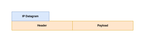
Now that we understood about the basics of IP datagram, let us look at the datagram structure in details for both the IPv4 and IPv6 packets.
IPv4 Datagram Format with 4 Octets per line
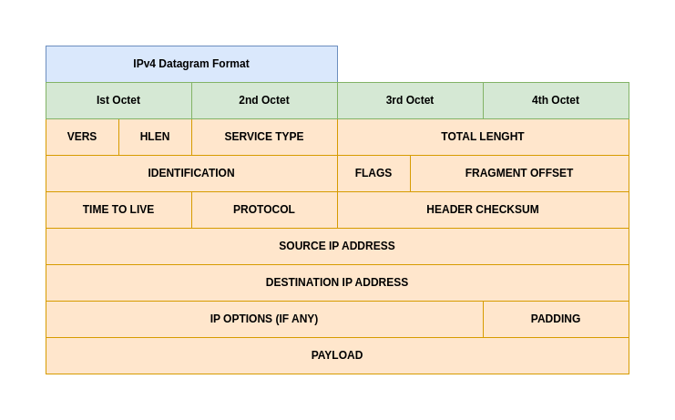
Let us try to understand a bit in details about the each Header field in IPv4 packet.
- VERS: It specifies the IP protocol version that is being used. For IPv4 the value is 4.
- HLEN: It specifies the Header length measured in 32 bit words.
- TOTAL LENGHT: It specifies the IP datagram size in octets, including both HEADER and PAYLOAD size.
- PROTOCOL: It specifies the value of the high level protocol that is used to create the message carried in the PAYLOAD of the datagram.
- HEADER CHECKSUM: It ensures the integrity of the header values. the IP header checksum does not protect against man-in-the-middle (MITM) attacks. Its sole purpose is to detect random, non-malicious data corruption that may occur during transmission (e.g., bit errors caused by network noise).
- SOURCE IP ADDRESS: It contains the 32 bit address of the sender
- DESTINATION IP ADDRESS: It contains the 32 bit address of the receiver
- PAYLOAD: It the data that is trasmitted within the datagram. The length varies depending upon the size of the message.
- OPTIONS: It is variable-length fields in the IPv4 header (up to 40 bytes) that provide extra functionality for network diagnostics, routing control, and security, extending the standard 20-byte header to a maximum of 60 bytes.
- PADDING: It represents bits containing zero that may be needed to ensure the datagram header extends to an exact multiple of 32 bits (recall that the header length field is specified in units of 32-bit words).
The most common datagram header, which contains no options and no padding, measures 20 octets and has a header length field equal to 5.
IPv6 Datagram Format with 4 Octets per line
IPv6 introduced Extension Headers into the datagram format.
These Extension Headers (EHs) provide a flexible, chained mechanism allowing the IETF to add new features (like security, mobility, or advanced routing) without changing the core header, making the protocol adaptable for future needs by simply defining new header types, which are processed by specific network nodes.
So, in short the IPv6 HEADERS field is not fixed but its adaptable to changing needs and included as required. Some of the extension headers are intended for processing by the ultimate destination and some of the extension headers are used by intermediate routers along the path.
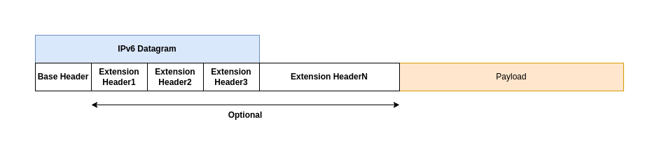
Each IPv6 header contains a NEXT HEADER field that specifies the type of the header that follows. The final header uses the NEXT HEADER field to specify the type of the payload.
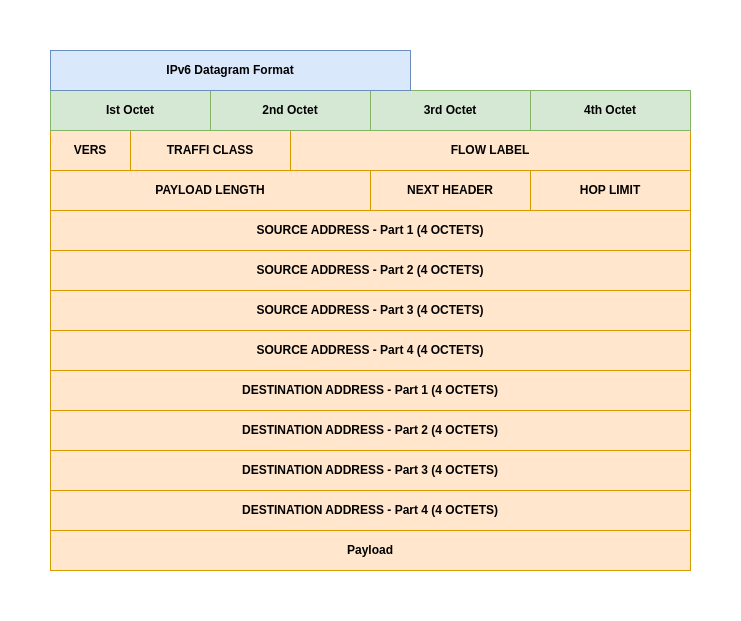
Each IPv6 datagram begins with a 40-octet base header. Let us now try to understand about the headers in IPv6 datagram.
- VERS: It specifies the version of the protocol in use. This value is 6 for IPv6 protocol.
- TRAFFIC CLASS: The Traffic Class field in IPv6 is an 8-bit field in the header, similar to IPv4’s Type of Service (ToS), used to classify and prioritize packets for Quality of Service (QoS) handling, helping routers manage congestion and ensure specific treatments for data like voice or video. It carries the Differentiated Services Code Point (DSCP) for 6 bits and Explicit Congestion Notification (ECN) for the last 2 bits, allowing for different priority levels and congestion signaling.
- FLOW LABEL: The FLOW LABEL holds an ID that allows a router to identify the flow, which is used instead of the destination address when forwarding a datagram.
- PAYLOAD LENGTH: It specifies the length of the data being carried and excludes the base or extension header length. To allow a payload to exceed 216 octets, IPv6 defines an extension header that specifies a datagram to be a jumbogram.
- HOP LIMIT: It specifies the maximum number of networks the datagram can traverse before being discarded.
- SOURCE ADDRESS: It specifies the 128 bit IPv6 address of the sender.
- DESTINATION ADDRESS: It specifies the 128 bit IPv6 address of the receiver.
IPv4 Type of Service or IPv6 Traffic Class
Type of Service or Traffic Class is a 8 bit field in both IPv4 and IPv6 datagram format. It specifies how a datagram needs to be handled.
In the late 1990s, the IETF redefined the meaning of the field to accommodate a set of differentiated services (DiffServ).
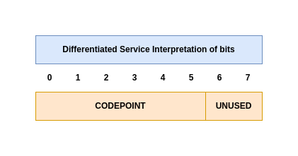
- CODEPOINT: A Differentiated Services Code Point (DSCP) is a 6-bit field in the IP header used for Quality of Service (QoS) to classify and manage network traffic, allowing routers to apply different forwarding treatments (Per-Hop Behaviors, or PHBs) to prioritize critical data like voice/video over less urgent data like email. A router might be configured with a voice service, a video service, a network management service, and a normal data service.
Even though with the representation of Type of Service or Traffic class, it is important to realize that forwarding software must choose from among the underlying physical network technologies at hand and must adhere to local policies. An internet does not guarantee to provide any particular type of service.
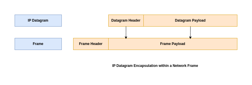
IP Datagram and Network Frame relation
Network Frames are handled by Physical Network Hardware and IP Datagrams are handled by the Higher Level Protocol software. As per the IPv4 datagram format we look at previously, it allocated 16 bits for TOTATL LENGTH field which means the IP Datagram max size can be at most 2^16 (ie. 65535 octets).
Encapsulation
To make internet transportation efficient, we would like to guarantee that each datagram travels in a distinct network frame. The idea of carrying one datagram in one network frame is called encapsulation, and is used with both IPv4 and IPv6.
Ethernet uses the type value 0x0800 to specify that the payload contains an encapsulated IPv4 datagram and 0x86DD to specify that the payload contains an IPv6 datagram.
The networking hardware through which a Frame is transferred has a specific upper bound limit based on the technology being used. Here are some examples.
- Ethernet limits transfers to 1500 octets of data.
- WiFi limits transfers to 128 octets of data.
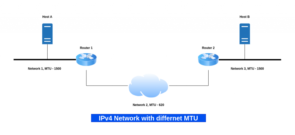
This limit is know as network’s maximum transfer unit, maximum transmission unit or MTU. Limiting datagrams to fit the smallest possible MTU in the internet makes transfers inefficient.
Fragmentation
TCP/IP came up with a solution for this know as Fragmentation. Instead of restricting datagram size, If the datagram size is less than the MTU size, it is encapsulated within the Frame and transferred. But if the datagram size is larger than the MTU size, the datagram is divided into smaller pieces called as Fragments.
A datagram may need to travel through different network paths having different MTU size limitation. In these situations it is important to consider the MTU along a path through internet.
- Path MTU: The path MTU is defined to be the minimum of the MTUs on networks along the path.
IPv4 allows any router along a path to fragment a datagram. But IPv6 requires the original source to learn the path MTU and perform fragmentation; routers are forbidden from performing fragmentation.
Instead of delayed fragmentation, IPv6 uses a form of early binding: the original source host is required to find the minimum MTU along the path to the destination and fragment each datagram according to the path it will take. A host must engage in a trial-and-error mechanism to determine the path MTU known as Path MTU Discovery (PMTUD).
Here are some additional fields related to IPv4 datagram that we can try to understand now.
- FLAGS: The IPv4 Flags field is a 3-bit section in the IP header controlling packet fragmentation, consisting of a reserved bit (always 0), the DF (Do Not Fragment) bit (1=Don’t fragment, 0=May fragment), and the MF (More Fragments) bit (1=More fragments follow, 0=Last fragment or no fragments). These flags, along with the Fragment Offset, help routers manage and receivers reassemble fragmented packets, ensuring data integrity across networks.
- OFFSET: IPv4 offset fields, primarily the 13-bit Fragment Offset, tell receiving hosts where a fragmented packet’s data belongs in the original, reassembled datagram, measured in 8-byte units from the start of the original data. Paired with the Flags field (specifically the More Fragments (MF) bit), it allows routers to split large packets and the destination to reconstruct them accurately, even if fragments arrive out of order, with the offset being 0 for the first fragment and increasing for subsequent ones.
- IDENTIFICATION: Field IDENTIFICATION contains a unique integer that identifies the datagram.
Fragmentation starts by replicating the original datagram header and then modifying the FLAGS and OFFSET fields.
Datagram Reassembly
The IP datagram once fragmented, each fragment travels as a separate datagram all the way to the ultimate destination where they are reassembled. There are two disadvantages to this approach of reassembly.
- Transporting small fragments on a network with large MTU cause network inefficency
- Datagram reassembly fails if any fragments get lost over the network
Reassembly timer: The ultimate destination starts a timer when a fragment arrives for a given datagram. If the timer expires before all fragments arrive, the receiving machine discards the surviving fragments. The sender now needs to send the datagram again.
In the Internet, the ultimate destination reassembles fragments. The design means that routers do not need to store fragments or keep other information about packets.
Three fields in an IPv4 datagram header or an IPv6 Fragment Extension Header control reassembly of datagrams: IDENTIFICATION, FLAGS (M in IPv6), and FRAGMENT OFFSET. Field IDENTIFICATION contains a unique integer that identifies the datagram.
Additional Fields
- TIME TO LIVE or HOP LIMIT: A TTL (Time-to-Live) value is a network setting that defines how long a data packet or record should exist or travel before being discarded, preventing endless circulation in routing loops and managing data caching, commonly seen in IP packets (as “HOP LIMIT”) and DNS records (in seconds).
Hope you enjoyed reading this article. Thank you..
Leave a Reply
You must be logged in to post a comment.